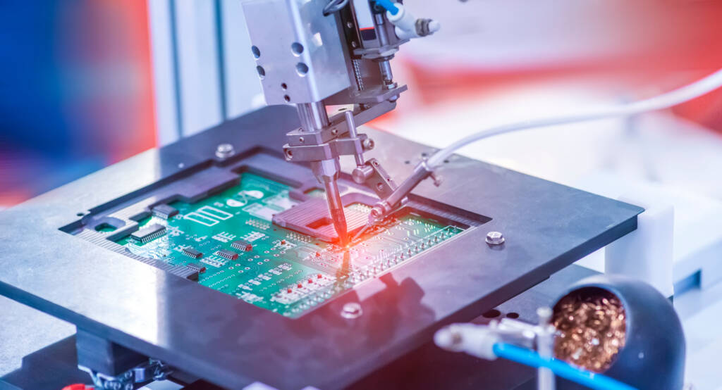
I was asked this week to contribute to the upcoming IPC handbook (IPC-CH-65 HDBK) on the section on contamination and its effects on printed wiring assemblies (PWA’s). There is a clear crossover of technology from the standard SMT / PCB arena into semiconductor assembly: specifically into flip-chip, microbumps and TSV assembly. However, the terminology is “starting to collide”: phrases familiar to semiconductor manufacturers now need to be understood and become part of the lexicon of semiconductor packaging engineers coming into the field from SMT. I want to set the record straight about this, hence this blog posting, which is based on a paper I gave at the IWLPC meeting in 2009, but probably bears repeating for a wider audience.
Electrochemical Migration (ECM)
ECM is characterized by the movement of metal ions BETWEEN adjacent metal conductors, to form dendrites. The key control parameters here are:
–Moisture or high humidity, measured as %RH
–Presence of mobile metal ions
–A high potential gradient, expressed in Volts per unit length (say V/cm)
High temperature may also exacerbate the problem. The hydrated metal ions, being positively charged, will migrate towards the cathode (-ve), forming a dendrite, which is a needle or tree-branch-like metal structure. The dendrite is the primary visual indicator of ECM. 
Electromigration (EM)
EM, on the other hand, occurs WITHIN a metal conductor, when large numbers of high-speed electrons impact on metal atoms and dislodge them by simple momentum transfer. The major factors effecting EM are:
–High temperature
–Presence of mobile metal atoms
–A high current density, expressed in Amps per unit area (say A/cm2)
It is important to note that humidity or other environmental moisture has no effect on EM, as EM occurs inside the metal joint.

The primary visual indicator of EM is the presence of voids at points in a metal interconnect near the anode (+ve), often where the current density is greatest (the “current crowding” effect – see below). 
The voids are usually seen inside the joint, and can eventually lead to thermal runaway and joint failure, as the effective cross-sectional area of the joint shrinks over time, increasing the current density.
I hope this explanation is clear and makes sense.
Cheers! Andy