Following on from our discussions of last time…
As you will recall from the previous post on this topic, My friend and colleague Chris Nash and I were discussing some puzzling results for low dip height found during testing of package-on-package (PoP) materials. The findings will be of interest to everyone who uses a dipping process in both SMT and flip-chip assembly.
For greater solder paste and flux dipping heights it appears as though a linear doctor blade (back and forth) used in a dipping process running at high speed will allow dip heights close to those expected from the theoretical engineered limit, for 50 microns and greater dip height. The high speed shear-thins the flux, which has the effect of both reducing the thickness of the boundary layer, and also has the benefit of reducing the extensional (tack) viscosity, so components can be more easily released from the dip tray.
What if you want to go to lower dip depths?
As we move into the area of copper pillar flip-chip dipping, and even (we hear) some Japanese customers doing package-on-package assembly, the dip height (dip depth) can go down to as low as 10-20microns, and this where we are hearing that rotary dip trays are coming into their own. The diagram below shows a simplified version of a flux and solder paste dipping tray.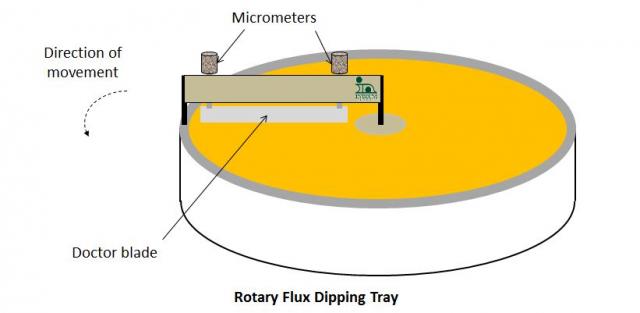
Rotary dip trays seem to have the following advantages:
– Height Setting: The dip height/depth is set using two micrometers, so is infinitely adjustable to a precise setting, although the dip height does have to be measured.
– Low Cost: They also add zero capital cost for a new dip depth setting, compared to specially-engineered dipping trays, which can be upwards of $2,000 each.
– Accuracy and Precision of Depth: From a more pragmatic viewpoint, however, the real reason for rotary trays being used with ultra-low dip heights is that the flux depth is actually measured: there is no tacit assumption of a given dip depth being correct and constant, based on the engineering of the dipping tray. As we saw last time, an error of 20 microns is possible, and with a dip height of 50 microns or less, this is a huge problem if you are using a 50 micron dip tray and assuming that you are getting exactly that dip depth.
However, rotary dip trays also have their share of potential problems compared to linear dipping systems:
– Larger Surface Area: Flux and solder paste may dry out faster, and a water soluble material will be more vulnerable to the humidity content of the air. It is also more wasteful of flux, since a larger surface area of flux is exposed than will ever be used, although this may also be true of some of the linear tray designs.
– Circular Tray: Materials will experience a higher shear rate at the outer edge than in the middle. If spun too fast, dipping materials may accumulate at the edges, thrown outwards by centripetal force.
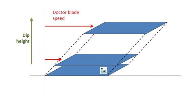
– Lower Shear Rate: For the same flux or solder paste dip depth, the velocity of the doctor blade will be much lower with a rotary than a linear system. However, as you can see from the illustration below, for a doctor blade moving at 1/4 the speed and 1/4 the dip height, the shear rate is the same.
As always, please contact me if you need to learn any more.
Cheers! Andy

