In a six-part SMT assembly series, we discussed the advantages of using fine powder solder pastes to improve process yields for stencil printing, especially in areas where the area ratio is below 0.66.
Because ~60% of solder defects typically occur at the printer, it is vital to success to focus on stencil printing. If insufficient paste is deposited, as is generally the case when observing these small apertures, the process has failed at the initial step in the SMT assembly, and rework is inevitable.
Finer powder solder pastes can help overcome the 0.66 constraint. However, as with most changes, there is a trade-off—reflow of these materials becomes more challenging.
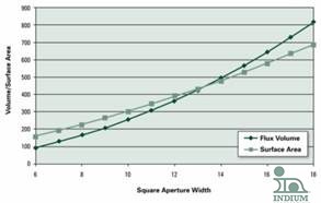
Figure 1
As we investigate, the reasons are understandable. First, as the particle size decreases, the total surface area (surface area exposed) for the same volume of solder paste increases. This increase in total surface area also means an increase in total surface oxide and the demand on the flux increases to remove those oxides. Second, as illustrated in Figure 1, the reason for choosing a finer powder solder paste is to print smaller apertures with challenging area ratios. As we read the chart from right to left, it can be seen that the ratio of available flux to the surface area exposed decreases as we move from an 18mil aperture to 6mil.
In other words there are two issues at work against us in reflowing finer powder solder pastes. The first is increased surface oxide within the paste itself. The second issue is the physical size of the solder paste deposit, which is smaller with less flux available and therefore, is much more sensitive to the oven environment.
Because of this we begin to experience solder defects associated with flux exhaustion: graping, head-in-pillow, de-wetting, solder balls, dull solder joints, and/or poor fillets.
With that said, anything we can do to diminish the total heat input will increase our process window for success. In other words, when possible and within reason:
- reduce the peak temperature
- shorten the time above liquidus
- shorten the total time in the heating portion of oven
- move as close as possible to a ramp to peak profile vs. soak profile
Again, remember these very small paste deposits are very sensitive to the oven environment.
Here are some basic tips. The preheat portion of the profile conditions the solder paste prior to reducing surface oxides and actual reflow. Ramping too quickly while the paste is still solvent-rich can cause small “explosions” and create solder balls/beads and flux spatter. Ramping too slowly and utilizing longer soaks can cause the paste to be exhausted prematurely. A ramp rate (not max(+)slope), or, should I say, an average rate from ambient to peak temperature of 1°C/s is a happy medium and makes the math quite easy; the assembly begins at an ambient temperature of 25°C and reflows at 245°C for Pb-free solder, a delta of 220 degrees. A ramp rate of 1°C/s means 220 degrees equals 220s or 3 minutes and 40 seconds; 4 minutes is a good target. The ramp rate can be adjusted by the conveyor speed, which is the total length of the heating portion of the oven divided by 4 minutes, giving us the belt speed. Fortunately, our BTU oven is 100 inches and equates to a belt speed of 25ipm (inches per minute).
Most oven manufactures suggest that the first zone be not less than 100°C to reduce flux vapors (condensation point). I prefer to start out less than 120°C to reduce solder paste “explosions” (large assemblies are an exception). I like to use the same delta between oven zones to create a gradual ramp (it also helps reduce delta T between components). An example is 110/130/150/170/190/210/230/250 and a belt speed of 25ipm (for our BTU oven suggested above) for a fairly simple board measuring 8" x 10" x 0.062" with a peak temperature at 235-245°C and time above liquidus of 45-70 seconds.
Of course, these are optimal settings and serve only as guidelines. There are always challenges such as very thick PCBs, large components, and very small components that require different soak profiles, longer total time in the oven, etc.
