Folks,
The creation of solder balls, when assembling passive discrete components, has been an issue for decades (see Figure 1). The discovery that the “home plate” stencil aperture design dramatically reduced the creation of solder balls was made quite a few years ago. More recently, the “inverted home plate” or “crown” design has been used with allegedly superior results. The “u-shaped aperture has been shown to reduce solder balling and have the added benefit of holding a cylindrical metal electrode leadless face (MELF) component in place and preventing rolling.
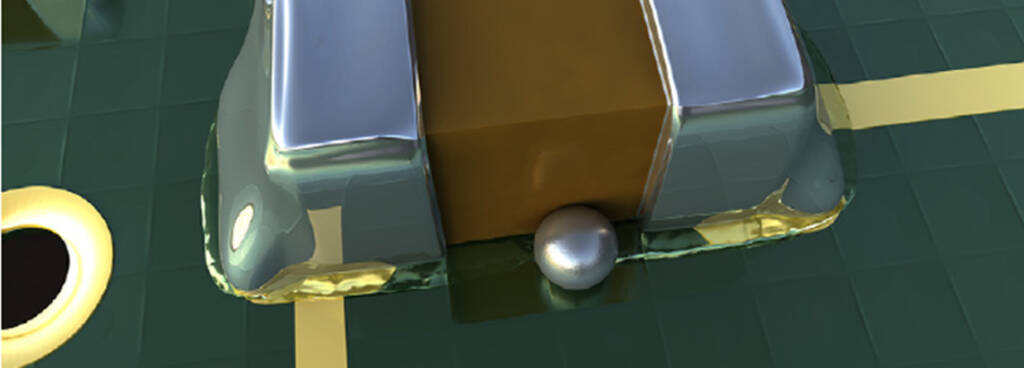
Figure 1. A solder ball near a passive component.
To calculate the parameters for the stencils for these three designs, I enhanced the Excel® spreadsheet StencilCoach™. To use StencilCoach™ in this regard, as an example, let’s look at the “inverted home plate” or “crown design” shown in Figure 2. The required inputs are in the blue cells D30-D34. Let’s enter the data for a 0402 passive (40 x 20 mils). In cell D30, we enter the maximum length, which is 42 mils. In cell D31, we enter the minimum length of 38 mils. In cell D32, we enter the maximum thickness of 14 mils, then the maximum width of 22 mils in cell D33. A stencil thickness of 5 mils is entered in cell D34. StencilCoach™ then calculates the various stencil and PWB pad parameters, as shown in Figure 2, in the gray cells. Note that StencilCoach™ even determines a suggested solder paste powder size in cell N35 and the area ratio in cell N31.
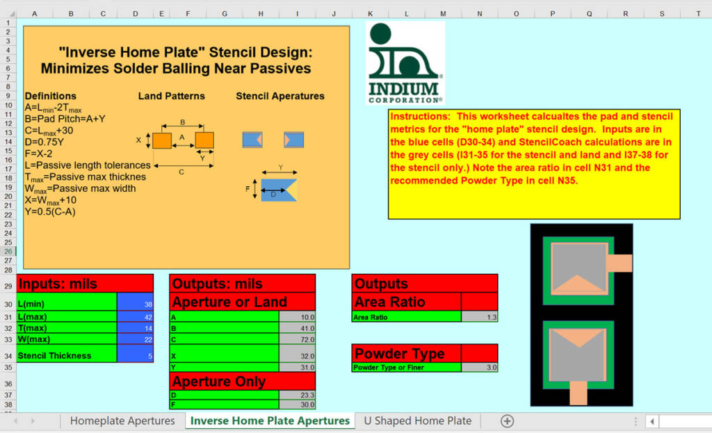
Figure 2. StencilCoach™ input and output for the “inverted home plate” aperture design.
See the parameters for the “home plate” and “u” designs for an 0402 passive in Figures 3 and 4.
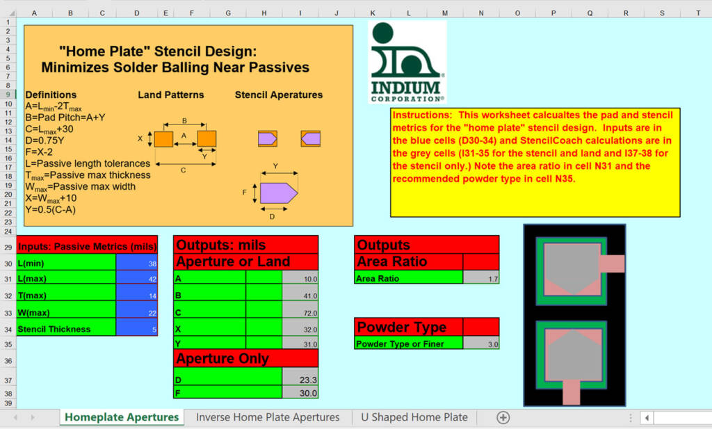
Figure 3. StencilCoach™ input and output for the “home plate” aperture design.
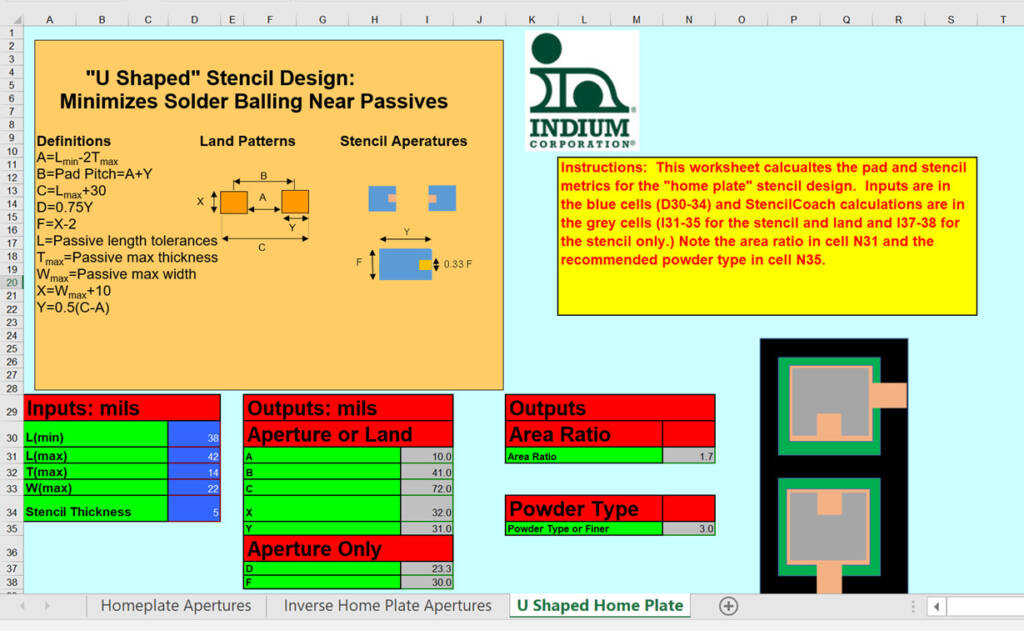
Figure 4. StencilCoach™ input and output for the “u” aperture design.
If you would like a copy of this version of StencilCoach™, send me an email at [email protected].
Cheers,
Dr. Ron
