Gente,
Dr. Ron: Per i prossimi post, vorrei chiacchierare con Jon Major, Product Manager di Indium Corporation per i materiali di interfaccia termica (TIM) in metallo, a proposito dei TIM in metallo. Jon, puoi parlarci un po' di te, del tuo background tecnico, di come sei entrato in contatto con Indium Corporation, di come ti sei interessato ai TIM e così via?
Jon: I’ve always been passionate about product development, engineering, materials, and manufacturing. I was fortunate enough to start my career in Silicon Valley, working with the brightest engineers on the planet; I had the opportunity to work on several groundbreaking products, such as the first iPad Air, the first cloud-based smartphone called the “Sidekick”, the first internet connected radio, and several other mobile devices, as well as an IoT platform for connected vehicles.
Jon: Thermal management was always considered at the design level, especially when dealing with consumer products. At Indium Corporation, I have the opportunity to dive deep, not only with the materials themselves, but how they perform with various surfaces, pressures, under varying warpage conditions, and how long they will survive under different use conditions. Our principal thermal engineer recently developed an in-house thermal test vehicle that provides the representative environment for examining performances of thermal interface materials. It’s rather fascinating! I was happy to be a part of a project that enables us to give our customers valuable data on how metal-based TIMs perform under varying conditions.
Dr. Ron: Jon, puoi spiegare brevemente perché i TIM metallici sono necessari e come funzionano?
Jon: As integrated circuit (IC) technology has advanced, the amount of heat generated by a high-performance IC is staggering, sometimes exceeding 1,000 watts when the IC is only slightly bigger than an inch (2.5 cm) on one side. The IC typically needs to operate at less than 100°C or its life will be too short. Without TIMs to conduct the heat away from the IC and to the heat-sink, this goal would be impossible.
(La Figura 1 mostra uno schema di un circuito integrato con due TIM che conducono il calore al dissipatore).
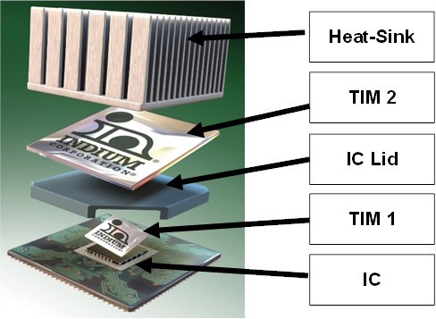
Figura 1. TIM1 conduce il calore dal circuito integrato al coperchio del pacchetto IC. TIM2 conduce il calore dal coperchio del pacchetto IC al dissipatore di calore.
Jon: In the past, polymeric (traditional) TIMs, gels, and other non-metal TIMs were used. In some applications, they are still used today. The most common was thermal grease, which has been used for many decades. Thermal grease has a carrier that is almost like Vaseline®. The carrier is loaded with conductive particles. The thermal grease is then applied where the metal TIMs are in Figure 1. Thermal grease has two shortcomings. One is that its thermal conductivity is not sufficient to meet higher-heat fluxes generated by high performance computing (HPC), AI, accelerated process unit (APU), and graphics processing unit (GPU) trends. The other is that the on/off cycles of electronics can cause “pump-out.” Pump-out occurs when the thermal grease is pumped-out from the space that it occupies to conduct heat away from the IC. With the thermal grease pumped out, it can no longer perform its function.
Jon: This is where metallic based TIMs come in. They can provide the lowest thermal resistance and be customized for package-specific needs. They also do not typically experience pump-out.
Jon: Con l'avanzamento dell'HPC, vediamo che i clienti devono affrontare ulteriori sfide dovute all'assottigliamento e alla curvatura degli stampi, al cross talk termico (calore proveniente da componenti vicini) e a varie altre sfide progettuali. La domanda di TIM a base metallica continua a crescere, perché possono risolvere molte di queste problematiche e fornire le prestazioni e l'affidabilità richieste nelle applicazioni ad alta densità di potenza.
Jon: Sebbene lo scopo principale di un TIM sia quello di contribuire a trasferire il calore da una superficie calda a una fredda, ci sono altri attributi da considerare in alcune applicazioni (ad esempio, facilità di montaggio, affidabilità, sostenibilità). I TIM a base metallica possono essere classificati come saldati (reflowed), comprimibili (non-reflowed), a base liquida (liquid metal TIM) o a cambiamento di fase. I TIM a cambiamento di fase sono progettati per cambiare fase quando si raggiunge una determinata temperatura. Tratteremo tutti questi TIM metallici nei prossimi post.
Jon: I TIM metallici hanno il vantaggio di avere alcune delle più alte conduttività termiche di massa tra i materiali TIM, ma è importante riconoscere che la sola conduttività termica di massa non è l'unico criterio per la scelta di un TIM. La resistenza al contatto termico, o resistenza interfacciale, domina in genere la resistenza termica complessiva del TIM. Pertanto, un'elevata bagnatura superficiale, per ridurre al minimo la resistenza al contatto termico, è un criterio critico per le prestazioni del TIM.
Dr. Ron: Daquanto ho capito, il TIM1 è solitamente un TIM a saldare. Può spiegare come funzionano?
Jon: TIM1 is commonly referred to as the interface between the backside of a die and the underside of an integrated heat spreader (IHS) and component cap. A soldered TIM (sTIM) at this interface is the “Cadillac” of TIMs. Once reflowed, sTIMs form intermetallic bonds that provide low interfacial resistance. Coupled with the fact that metal-based TIMs have high bulk thermal conductivity, the sTIM provides very low overall thermal resistance. sTIMs also mechanically fasten the die and IHS together given there is an intermetallic compound (IMC) formed at the interface. Often, we are asked if the rigidity of the solder joint could cause problems during power cycling. With the proper alloy and process, the sTIM can provide the ductility necessary during the life of the package, so rigidity issues are not a concern.
Jon: There are many process considerations when selecting a sTIM. Indium Corporation has the experience and guidelines to help customers realize the benefits of sTIMs. One of the challenges in assembling TIM1s is voiding during reflow (see Figure 2). Voiding becomes worse after multiple reflows.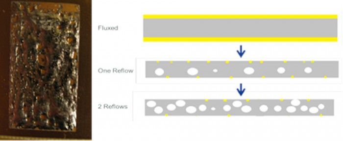
Figura 2. TIM1 è collocato tra il chip (o die) e l'IHS.
Dr. Ron: So che ci sono stati dei progressi nella riduzione della minzione, può spiegare?
Jon: Storicamente, gli sTIM venivano utilizzati principalmente in pacchetti di tipo LGA o PGA. Questi pacchetti venivano sottoposti a rifusione una volta per rifondere lo sTIM. A causa dei vantaggi offerti dagli sTIM, si sta cercando di trovare un materiale sTIM e un processo ottimali per i pacchetti che possono sopravvivere a più cicli di rifusione BGA, in genere con una temperatura di picco di 240-250°C. Ad ogni successivo reflow, i materiali sTIM tradizionali presentano una crescita dei vuoti che porta a prestazioni termiche scadenti.
(Le leghe di InAg mostrano un miglioramento significativo rispetto all'indio puro per ridurre la crescita dei vuoti nei riflussi successivi). Si veda la Figura 3).
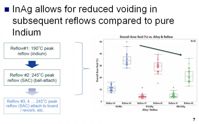
Figura 3. I TIM1 InAg riducono significativamente la minzione rispetto ai TIM1 In.
Jon: However, there are trade-offs to adding Ag to the solder joint. More Ag also means lower bulk thermal conductivity and a more rigid solder joint leading to reduced mechanical reliability. There is significant research underway to understand how different compositions of InAg wet to various surfaces and how they perform during reliability testing. High surface wetting, to minimize thermal contact resistance, is a critical TIM performance criterion. In addition, poor wetting can result in higher voiding, also leading to poor thermal performance. With the proper alloys selection, flux and process considerations sTIM can be adopted in Flip Chips BGA(FCBGA)style packages that will undergo multiple reflow cycles (see Figure 4).
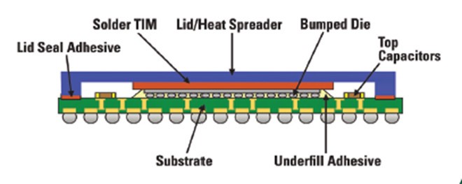
Figura 4. Gli InAg sTIM si adattano bene agli FCBGA.
Gente,
Restate sintonizzati per il prossimo post su mTIMS1.5!
Salute,
Dr. Ron