皆さん、
ロン博士今回から数回にわたって、インジウム・コーポレーションの金属熱界面材料(TIMs)製品マネージャー、ジョン・メジャー氏と金属TIMsについてお話ししたいと思います。ジョンさん、技術的な経歴、インジウム・コーポレーションとの出会い、TIMに興味を持ったきっかけなど、ご自身のことを少し教えていただけますか?
Jon: I’ve always been passionate about product development, engineering, materials, and manufacturing. I was fortunate enough to start my career in Silicon Valley, working with the brightest engineers on the planet; I had the opportunity to work on several groundbreaking products, such as the first iPad Air, the first cloud-based smartphone called the “Sidekick”, the first internet connected radio, and several other mobile devices, as well as an IoT platform for connected vehicles.
Jon: Thermal management was always considered at the design level, especially when dealing with consumer products. At Indium Corporation, I have the opportunity to dive deep, not only with the materials themselves, but how they perform with various surfaces, pressures, under varying warpage conditions, and how long they will survive under different use conditions. Our principal thermal engineer recently developed an in-house thermal test vehicle that provides the representative environment for examining performances of thermal interface materials. It’s rather fascinating! I was happy to be a part of a project that enables us to give our customers valuable data on how metal-based TIMs perform under varying conditions.
ロン博士 ジョン、なぜメタルTIMが必要なのか、どのように機能するのか、簡単に説明してもらえますか?
Jon: As integrated circuit (IC) technology has advanced, the amount of heat generated by a high-performance IC is staggering, sometimes exceeding 1,000 watts when the IC is only slightly bigger than an inch (2.5 cm) on one side. The IC typically needs to operate at less than 100°C or its life will be too short. Without TIMs to conduct the heat away from the IC and to the heat-sink, this goal would be impossible.
(図1は、ヒートシンクに熱を伝える2つのTIMを持つICの回路図である)
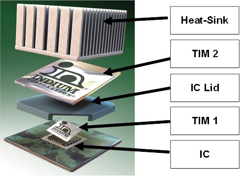
図1.TIM1はICからICパッケージの蓋に熱を伝導する。TIM2はICパッケージの蓋からヒートシンクに熱を伝導する。
Jon: In the past, polymeric (traditional) TIMs, gels, and other non-metal TIMs were used. In some applications, they are still used today. The most common was thermal grease, which has been used for many decades. Thermal grease has a carrier that is almost like Vaseline®. The carrier is loaded with conductive particles. The thermal grease is then applied where the metal TIMs are in Figure 1. Thermal grease has two shortcomings. One is that its thermal conductivity is not sufficient to meet higher-heat fluxes generated by high performance computing (HPC), AI, accelerated process unit (APU), and graphics processing unit (GPU) trends. The other is that the on/off cycles of electronics can cause “pump-out.” Pump-out occurs when the thermal grease is pumped-out from the space that it occupies to conduct heat away from the IC. With the thermal grease pumped out, it can no longer perform its function.
Jon: This is where metallic based TIMs come in. They can provide the lowest thermal resistance and be customized for package-specific needs. They also do not typically experience pump-out.
ジョン:HPCの進歩に伴い、ダイの薄型化や反り、サーマルクロストーク(隣接する部品からの熱)、その他さまざまな設計上の課題により、お客様がさらなる課題を抱えていることを目の当たりにしています。メタルベースTIMは、これらの課題の多くを解決し、高電力密度アプリケーションで求められる性能と信頼性を提供できるため、需要は伸び続けています。
ジョン: TIM の主な目的は、高温の表面から低温の表面への熱伝導を助けることですが、用途によっては他の特性も考慮する必要があります(組み立ての容易さ、信頼性、持続可能性など)。金属ベースのTIMは、はんだ付け(リフロー)、圧縮性(非リフロー)、液体ベース(液体金属TIM)、または相変化TIMに分類することができます。相変化TIMは、ある温度に達すると相変化するように設計されています。これらすべてのメタルTIMについては、今後の記事で取り上げる予定です。
ジョン:メタルTIMはTIM材料の中で最も高いバルク熱伝導率を持つという利点がありますが、バルク熱伝導率だけがTIM選択の唯一の基準ではないことを認識することが重要です。熱接触抵抗、すなわち界面抵抗は通常、TIM全体の熱抵抗を支配します。したがって、熱接触抵抗を最小化するための高い表面濡れ性は、TIMの性能基準として極めて重要です。
ロン博士:私の理解では、TIM1は通常はんだTIMです。どのように機能するのか説明してもらえますか?
Jon: TIM1 is commonly referred to as the interface between the backside of a die and the underside of an integrated heat spreader (IHS) and component cap. A soldered TIM (sTIM) at this interface is the “Cadillac” of TIMs. Once reflowed, sTIMs form intermetallic bonds that provide low interfacial resistance. Coupled with the fact that metal-based TIMs have high bulk thermal conductivity, the sTIM provides very low overall thermal resistance. sTIMs also mechanically fasten the die and IHS together given there is an intermetallic compound (IMC) formed at the interface. Often, we are asked if the rigidity of the solder joint could cause problems during power cycling. With the proper alloy and process, the sTIM can provide the ductility necessary during the life of the package, so rigidity issues are not a concern.
ジョン There are many process considerations when selecting a sTIM. Indium Corporation has the experience and guidelines to help customers realize the benefits of sTIMs. One of the challenges in assembling TIM1s is voiding during reflow (see Figure 2). Voiding becomes worse after multiple reflows.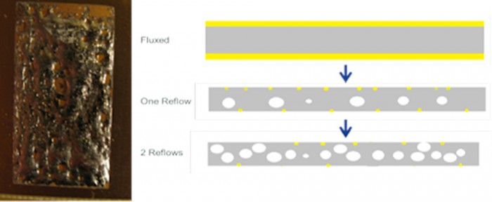
図 2.TIM1 はチップ(またはダイ)と IHS の間に配置される。
ロン博士: 排泄を減らす画期的な方法があるそうですが、説明していただけますか?
ジョン: 歴史的に、sTIMは主にLGAやPGAスタイルのパッケージで使われていました。これらのパッケージは、sTIMをリフローするために一度リフローされていました。sTIMには利点があるため、ピーク温度240~250℃のBGAリフローサイクルに複数回耐えられるパッケージ用の最適なsTIM材料とプロセスを見つける努力がなされています。その後のリフローのたびに、従来のsTIM材料はボイドの成長を示し、熱性能の低下につながります。
(InAg合金は、純インジウムと比較して、その後のリフローでのボイド成長を低減するために著しい改善を示している。図3参照)。
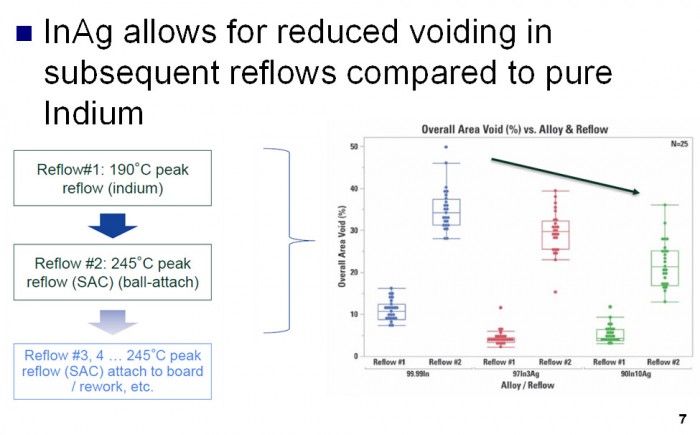
図3.InAg TIM1はIn TIM1に比べて有意に排泄を抑制する。
Jon: However, there are trade-offs to adding Ag to the solder joint. More Ag also means lower bulk thermal conductivity and a more rigid solder joint leading to reduced mechanical reliability. There is significant research underway to understand how different compositions of InAg wet to various surfaces and how they perform during reliability testing. High surface wetting, to minimize thermal contact resistance, is a critical TIM performance criterion. In addition, poor wetting can result in higher voiding, also leading to poor thermal performance. With the proper alloys selection, flux and process considerations sTIM can be adopted in Flip Chips BGA(FCBGA)style packages that will undergo multiple reflow cycles (see Figure 4).
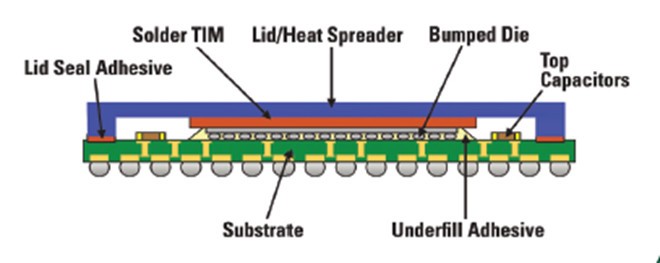
図4.InAg sTIMはFCBGAに適している。
皆さん、
mTIMS1.5に関する次回の記事にご期待ください!
乾杯
ロン博士