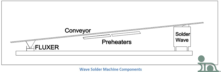
Es gibt viele Arten von Wellenlötmaschinen, jede mit ihren eigenen Macken, Eigenschaften und Persönlichkeiten. Die gute Nachricht ist, dass alle die gleichen Kernelemente des Prozesses haben, was den Vergleich verschiedener Modelle erleichtert (wenn auch nicht ganz einfach):
- Fluxing
- Vorwärmen
- Löten
- Fördern
I will be discussing all of these elements, in detail, throughout this series. By breaking wave solder machines down to these elements, it is possible to compare a large number of machines, based on certain process characteristics of the different types of fluxers, preheaters, etc.
T
Fluxers – An Introduction
Flux is an essential component in the creation of a solder joint. For the sake of this post, I will be referencing flux as it is used in wave soldering machines. But, if you want to know of other uses, check out my colleague, Jim Hisert’s, blog: Specifying Solder Preforms – Flux.
Als das Wellenlöten entwickelt wurde, wurde das Flussmittel in der Regel mit einer Pinselmethode aufgetragen, bei der ein Techniker das Flussmittel mit einem Pinsel auftrug. Wie Sie sich vorstellen können, war dies nicht gerade ein kontrollierter Vorgang. Um die Produktivität, Genauigkeit und Konsistenz beim Auftragen des Flussmittels zu erhöhen, war eine Automatisierung erforderlich. Die verschiedenen Methoden, die in dieser Serie vorgestellt und diskutiert werden, sind:
- Schaumstoff-Flussmittel
- Wellenfluxer
- Sprüh-Flussmittel
- Bürsten-Fluxer

Wenn die Automatisierung in Gang kommt, müssen bestimmte Vorschriften umgesetzt werden, z. B. die Betriebsvorschriften für Fluxer, die Flussmittelzugabe und die Flussdichtekontrolle. Es gibt auch bestimmte Strategien, die umgesetzt werden, wie das Total Loss System, das parallel zum Sprühfluxer diskutiert wird.
Schaumstoff-Fluxer
A wave solder machine’s foam fluxer is a device in which compressed air is fed through a porous tube (commonly referred to as a “stone” because this part used to be made out of unglazed porcelain) that is submerged in foaming flux. The stone is covered with a chimney which helps produce a cascading head of flux foam.A basic foaming flux schematic can be seen in the drawing.
Nicht alle Flussmittel eignen sich für dieses Szenario. Das Flussmittel muss eine schäumende Eigenschaft haben, die entweder bei der Entwicklung oder durch den Zusatz eines Schaumbildners erzeugt wird. Wenn das richtige Flussmittel verwendet wird, tritt das Flussmittel aus der Schütte aus und bildet einen Schaumkopf. Dieser muss ordnungsgemäß gewartet werden, um eine genaue Flussmittelabscheidung auf der Leiterplatte zu gewährleisten.
Nach dem Wellenkopf folgt in der Regel ein Luftmesser oder eine Bürste, um überschüssiges Flussmittel von der Leiterplatte zu entfernen. Wenn die Leiterplatte mit überschüssigem Flussmittel betropft ist, kann das Flussmittel auf die Vorheizungen tropfen. Eingebranntes Flussmittel ist extrem schwer zu entfernen. Außerdem sind bestimmte Flussmittel flüchtig und entflammbar. Die mit diesen Flussmitteln verbundenen Sicherheitsrisiken sind hoch.
Der Schaumkopf ist schwer zu warten; er kann für die Bediener eine echte Herausforderung darstellen. Daher sollte die Luftzufuhr des Fluxers langsam eingestellt werden, wenn eine genaue Schaumkopfkonsistenz erreicht werden soll. Wenn wir eine große Menge Luft einführen, ohne sie richtig aufzubauen, können wir große Blasen erzeugen. Wenn diese Blasen die Spitze des Schaums erreichen, zerplatzen sie. Der Schaum ist sehr hitzeempfindlich. Wenn eine heiße Palette, Vorrichtung oder Platte mit dem Schaumstoff in Berührung kommt, kann der Schaumstoffkopf zusammenbrechen. Der Schaumkopf kann sich erholen, braucht aber Zeit, um sich wieder aufzubauen. Wenn der Bediener den Zusammenbruch nicht bemerkt, kann es durchaus vorkommen, dass bestimmte Leiterplatten nicht ausreichend oder gar nicht mit Flussmittel versehen sind, was zu einer schlechten Lötung führt.
Die Poren des Steins sind fein und können leicht durch trockenes Flussmittel verstopft werden; trockenes Flussmittel lässt sich nur sehr schwer, wenn überhaupt, entfernen. Wenn die Maschine abgeschaltet werden muss (aus welchem Grund auch immer, einschließlich routinemäßiger Wartungsarbeiten), sollte der Fluxer entleert und gründlich gereinigt werden, um dieses Problem zu vermeiden. Auch wenn die Druckluft im Stein mit Öl oder Wasser verunreinigt ist, wird das Flussmittel beeinträchtigt und funktioniert nicht mehr richtig. Wenn ein anständiger Schaumkopf schwer zu erreichen ist, sollte Verschmutzung der erste Verdacht sein.
Wellenfluxer
When the wave soldering machine was developed, the early flux application method was the same as the solder application method – a wave. While this technique is not common these days, it still finds some use. So, let’s discuss it.
First, how it works: The mechanism consists of a container, a pump, and a nozzle (to create the flux wave effect) – just like a solder wave mechanism. The bottom of the PCB is passed over the wave and coated with a thin layer of flux. This ensures that components on the top remain flux-free.This image shows shows the top view of a wave fluxer, with an air knife attached.
In this design, the air knife is essential because the wave fluxer emits a large amount of flux. The air knife helps contain excess flux. If excess flux were to drip from the fluxed PCBs into the machine, it would create a hard-to-clean mess. In addition, the air knife prevents excess flux from dripping onto the preheaters. Some fluxes are volatile and could cause fires within the machine. A mesh above the fluxer decreases chances of any wave defects, such as ripples, and ensures even flux distribution.
The benefits to having a wave fluxer are:
- The flux doesn’t need any foaming agents
- It is possible to flux boards that have long leads or pins (through-hole)
- The bottom of the board will be coated in a continuous layer of flux
- It can create a head that is significantly deeper than that of a foam fluxer
- Flux contamination will not affect the amount of flux applied to the bottom of the board
When the foam fluxer malfunctions, it is relatively easy to detect, due to the foam head state. But, with a wave fluxer, it is nearly impossible to visually determine if conditions are out of specified tolerances. Constant monitoring is required.
Sprüh-Flussmittel
Spray Fluxing is the most common way to flux a printed circuit board today. When spray fluxers were first developed they were clumsy, inefficient machines. They were messy and required a lot of maintenance. In addition, spray fluxers require separate venting from the main portion of the wave solder machine and a “total loss” system is used, especially when using no-clean flux. Ralph Woodgate’s book The Handbook of Machine Soldering SMT and TH mentions that, “the main systems fall into the following categories:
- The compressed air spray total loss system.
- The ultrasonic spray total loss system.
- The airless spray total loss system.
- The drum and air knife spray recirculating system.”
Some of the advantages of using a spray fluxer are:
- The spray fluxer may be programmed to cover specific areas of the PCB. This is helpful if selective soldering is to be achieved.
- The quantity of flux can be changed based on specific process characterizations.
Spray fluxers move perpendicular to the conveyor movement. This, combined with the desire to apply the effective minimum amount of flux, ensures even and proper wetting. This is beneficial for many reasons, including:
- It conserves operational costs.
- Better wetting is achieved when there is less flux residue.
- Longer component leads are fluxed easily.
The Total Loss System and Spray Fluxing
The total loss system is a method of applying spray flux that utilizes the minimal amount of material to properly create a satisfactory solder joint. In this process, the flux is sprayed directly onto the PCB from a sealed container. All of the flux from the container is used, either by applying it to the board or it is lost from over spray. This is the main reason why there needs to be a separate venting system for the lost flux removal.
Open systems for applying flux had problems that the total loss spray fluxing system solved. The benefits of using spray fluxers and the total loss system are:
- Can be used with fluxes that don’t foam well
- No need to monitor density
- Titration and chemical measurements of the acid content are unnecessary
All of the above methods were expensive to operate. By not recirculating the flux, the cost and work associated with the tests were eliminated. If the process is set up correctly, all of the flux sprayed on the board will have the same characteristics as the unopened container.
All systems can vary when being used by different consumers because they have different wants and needs for their applications and processes.
There are two distinct variations in the total loss system. One nozzle is used to produce a high-pressure fan-shaped spray pattern that covers the entire width of the board and is rapidly pulsed. This ensures an even layer of flux. The other nozzle is moved from side to side to cover the board area. A diagram is seen in the previous section. They are similar in that fresh flux is sprayed through a nozzle or misted onto the bottom of the PCB. Some spray fluxers mix in some air to help form the mist while others use compressed air to guide the spray. Some apply pressure to the flux in lieu of compressed air.
There are also ultrasonic spray fluxers which use an entirely different approach than mentioned above to disperse the flux. The nozzle utilizes ultrasonic energy to break down the flux into a spray pattern where compressed air forces the droplets into a fan shape for even distribution. It eliminates the mechanics involved in moving the flux nozzle by using certain sensors. The spray therefore only operates when the board is in the right place at the right time. Any other time it is shut off; this minimizes waste of the flux and the loss associated with the total loss system.
Spray Fluxer Venting
No matter how accurate the spray fluxer is there will at least be some flux that is not deposited on the board that needs to be removed from the system. I mentioned in the previous section that all spray fluxer setups need to have their own venting system, separate from the soldering station vent system.
The diagram that I created here shows a simple schematic of what the venting system might look like. The horizontal plates, the first filters in the vent, are removable and can be cleaned of the flux residue. Some of the more sophisticated systems may have three or more plates. Some flux may be able to bypass the plates and get into the duct work. That is why it is important to have a system that can be easily disassembled and thoroughly cleaned. If the flux is not removed it can pose a fire and safety hazard. In the event of a fire, the duct work should have a fusible link that would shut off the vent fans. Also, since the flux can be very corrosive, the material you use for the vent and duct work should be considered appropriately.
Brush Fluxer
The last two sections have been about the different facets of spray fluxing and the systems that are used. In this post, we are moving on from spray fluxing and discussing the final type of fluxer in this mini-series: a brush fluxer. It is, arguably, the oldest form of fluxing and it is rarely used today.
In the early days of circuit board assembly, flux was applied using, basically, a paintbrush. The system that I will be talking about is slightly more sophisticated than that. You can catch a glimpse of this system from the schematic you see here.
I like to think of it as an automated paint roller. The cylindrical brush is half-submerged in a bath of flux and is rotating on its center axis. The board contacts the brush at the apex and moves opposite the brush’s rotational direction at the point of tangency. The flux deposition can vary significantly. This unpredictability is one of the reasons that it is not being used today.
This system is a recirculating system with the same problems that are associated with other open systems, such as foaming or wave. Also, the brush has to be washed very thoroughly. Have you ever left a paintbrush or roller out after painting, only to come back hours later unable to use it? Brush fluxers follow similar logic. For today’s modern SMT designed circuit boards, this system is archaic and unsuitable. However, it is used in special circumstances that need a low-cost application method for simple product assemblies, or when you are unable to use the more modern methods.
This will complete the fluxer section of my blog.