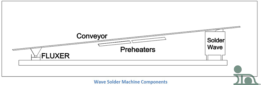
There are many types of wave solder machines, each with their own quirks, characteristics, and personalities. The good news is, each has the same core process elements, making it easier (maybe not easy) to compare different models:
- Fluxing
- Preheating
- Soldering
- Conveying
I will be discussing all of these elements, in detail, throughout this series. By breaking wave solder machines down to these elements, it is possible to compare a large number of machines, based on certain process characteristics of the different types of fluxers, preheaters, etc.
T
Fluxers – An Introduction
Flux is an essential component in the creation of a solder joint. For the sake of this post, I will be referencing flux as it is used in wave soldering machines. But, if you want to know of other uses, check out my colleague, Jim Hisert’s, blog: Specifying Solder Preforms – Flux.
When wave soldering was first developed, the flux was commonly applied using a brush method in which a technician would apply the flux using, you guessed it, a paint brush. As you can imagine, this was not the most controlled operation. Automation was needed to increase productivity, accuracy, and consistency when applying flux. The different methods created and discussed in this series are:
- Foam Fluxers
- Wave Fluxers
- Spray Fluxers
- Brush Fluxers

When automation is initiated, certain regulations need to be implemented, such as the operating rules for fluxers, along with flux addition and flux density control. There are also certain strategies that are implemented, like the total loss system that will be discussed in parallel with the spray fluxer.
Foam Fluxer
A wave solder machine’s foam fluxer is a device in which compressed air is fed through a porous tube (commonly referred to as a “stone” because this part used to be made out of unglazed porcelain) that is submerged in foaming flux. The stone is covered with a chimney which helps produce a cascading head of flux foam.A basic foaming flux schematic can be seen in the drawing.
Not all fluxes will work well in this scenario. The flux needs to have a foaming characteristic, either instituted in development or by the addition of a foaming agent. If the correct flux is used, then the flux will bubble out of the chute and create a foam head. This needs to be properly maintained to assure accurate flux deposition on the board.
There is usually an air knife or a brush following the wave head to remove any surplus from the PCB. If the printed circuit board is dripping with excess flux, the flux can drip onto the preheaters. Burned-on flux is extremely hard to remove. Also, certain fluxes are volatile and flammable. The safety risks associated with those types of fluxes are high.
The foam head is difficult to maintain; it can present a real challenge to operators. To address this, the fluxer’s air supply should be adjusted slowly, if accurate head consistency is to be achieved. By introducing a large amount of air without proper buildup, we can produce large bubbles. When these bubbles reach the top the foam, they burst. The foam is very sensitive to heat. If a hot pallet, fixture, or board comes in contact with the foam, the foam head could collapse. The foam head can recover but requires time to build up again. If the operator does not notice the collapse, then there very well might be certain printed circuit board assemblies that will not have adequate, or any, flux, resulting in poor soldering.
The stone’s pores are fine and can easily be clogged with dry flux; dry flux can be very difficult, if not impossible, to remove. If the machine is to be shut down (for any reason, including routine maintenance), the fluxer should be drained and cleaned extensively to avoid this problem. Also, if the compressed air in the stone is contaminated with oil or water, the flux will become compromised and not perform correctly. If a decent foam head is hard to achieve, contamination should be the first suspect.
Wave Fluxers
When the wave soldering machine was developed, the early flux application method was the same as the solder application method – a wave. While this technique is not common these days, it still finds some use. So, let’s discuss it.
First, how it works: The mechanism consists of a container, a pump, and a nozzle (to create the flux wave effect) – just like a solder wave mechanism. The bottom of the PCB is passed over the wave and coated with a thin layer of flux. This ensures that components on the top remain flux-free.This image shows shows the top view of a wave fluxer, with an air knife attached.
In this design, the air knife is essential because the wave fluxer emits a large amount of flux. The air knife helps contain excess flux. If excess flux were to drip from the fluxed PCBs into the machine, it would create a hard-to-clean mess. In addition, the air knife prevents excess flux from dripping onto the preheaters. Some fluxes are volatile and could cause fires within the machine. A mesh above the fluxer decreases chances of any wave defects, such as ripples, and ensures even flux distribution.
The benefits to having a wave fluxer are:
- The flux doesn’t need any foaming agents
- It is possible to flux boards that have long leads or pins (through-hole)
- The bottom of the board will be coated in a continuous layer of flux
- It can create a head that is significantly deeper than that of a foam fluxer
- Flux contamination will not affect the amount of flux applied to the bottom of the board
When the foam fluxer malfunctions, it is relatively easy to detect, due to the foam head state. But, with a wave fluxer, it is nearly impossible to visually determine if conditions are out of specified tolerances. Constant monitoring is required.
Spray Fluxers
Spray Fluxing is the most common way to flux a printed circuit board today. When spray fluxers were first developed they were clumsy, inefficient machines. They were messy and required a lot of maintenance. In addition, spray fluxers require separate venting from the main portion of the wave solder machine and a “total loss” system is used, especially when using no-clean flux. Ralph Woodgate’s book The Handbook of Machine Soldering SMT and TH mentions that, “the main systems fall into the following categories:
- The compressed air spray total loss system.
- The ultrasonic spray total loss system.
- The airless spray total loss system.
- The drum and air knife spray recirculating system.”
Some of the advantages of using a spray fluxer are:
- The spray fluxer may be programmed to cover specific areas of the PCB. This is helpful if selective soldering is to be achieved.
- The quantity of flux can be changed based on specific process characterizations.
Spray fluxers move perpendicular to the conveyor movement. This, combined with the desire to apply the effective minimum amount of flux, ensures even and proper wetting. This is beneficial for many reasons, including:
- It conserves operational costs.
- Better wetting is achieved when there is less flux residue.
- Longer component leads are fluxed easily.
The Total Loss System and Spray Fluxing
The total loss system is a method of applying spray flux that utilizes the minimal amount of material to properly create a satisfactory solder joint. In this process, the flux is sprayed directly onto the PCB from a sealed container. All of the flux from the container is used, either by applying it to the board or it is lost from over spray. This is the main reason why there needs to be a separate venting system for the lost flux removal.
Open systems for applying flux had problems that the total loss spray fluxing system solved. The benefits of using spray fluxers and the total loss system are:
- Can be used with fluxes that don’t foam well
- No need to monitor density
- Titration and chemical measurements of the acid content are unnecessary
All of the above methods were expensive to operate. By not recirculating the flux, the cost and work associated with the tests were eliminated. If the process is set up correctly, all of the flux sprayed on the board will have the same characteristics as the unopened container.
All systems can vary when being used by different consumers because they have different wants and needs for their applications and processes.
There are two distinct variations in the total loss system. One nozzle is used to produce a high-pressure fan-shaped spray pattern that covers the entire width of the board and is rapidly pulsed. This ensures an even layer of flux. The other nozzle is moved from side to side to cover the board area. A diagram is seen in the previous section. They are similar in that fresh flux is sprayed through a nozzle or misted onto the bottom of the PCB. Some spray fluxers mix in some air to help form the mist while others use compressed air to guide the spray. Some apply pressure to the flux in lieu of compressed air.
There are also ultrasonic spray fluxers which use an entirely different approach than mentioned above to disperse the flux. The nozzle utilizes ultrasonic energy to break down the flux into a spray pattern where compressed air forces the droplets into a fan shape for even distribution. It eliminates the mechanics involved in moving the flux nozzle by using certain sensors. The spray therefore only operates when the board is in the right place at the right time. Any other time it is shut off; this minimizes waste of the flux and the loss associated with the total loss system.
Spray Fluxer Venting
No matter how accurate the spray fluxer is there will at least be some flux that is not deposited on the board that needs to be removed from the system. I mentioned in the previous section that all spray fluxer setups need to have their own venting system, separate from the soldering station vent system.
The diagram that I created here shows a simple schematic of what the venting system might look like. The horizontal plates, the first filters in the vent, are removable and can be cleaned of the flux residue. Some of the more sophisticated systems may have three or more plates. Some flux may be able to bypass the plates and get into the duct work. That is why it is important to have a system that can be easily disassembled and thoroughly cleaned. If the flux is not removed it can pose a fire and safety hazard. In the event of a fire, the duct work should have a fusible link that would shut off the vent fans. Also, since the flux can be very corrosive, the material you use for the vent and duct work should be considered appropriately.
Brush Fluxer
The last two sections have been about the different facets of spray fluxing and the systems that are used. In this post, we are moving on from spray fluxing and discussing the final type of fluxer in this mini-series: a brush fluxer. It is, arguably, the oldest form of fluxing and it is rarely used today.
En los primeros tiempos del montaje de placas de circuitos, el fundente se aplicaba utilizando, básicamente, un pincel. El sistema del que voy a hablar es algo más sofisticado que eso. Puedes echar un vistazo a este sistema desde el esquema que ves aquí.
Me gusta pensar en él como un rodillo de pintura automatizado. La brocha cilíndrica está medio sumergida en un baño de fundente y gira sobre su eje central. La placa entra en contacto con la brocha en el vértice y se desplaza en sentido contrario al de rotación de la brocha en el punto de tangencia. La deposición de fundente puede variar considerablemente. Esta imprevisibilidad es una de las razones por las que no se utiliza hoy en día.
Este sistema es un sistema de recirculación con los mismos problemas que se asocian a otros sistemas abiertos, como la formación de espuma o la ondulación. Además, la brocha tiene que lavarse muy a fondo. ¿Alguna vez ha dejado una brocha o un rodillo fuera después de pintar, para volver horas más tarde sin poder utilizarlo? Los fundentes de brocha siguen una lógica similar. Para las modernas placas de circuito diseñadas para SMT de hoy en día, este sistema es arcaico e inadecuado. Sin embargo, se utiliza en circunstancias especiales que necesitan un método de aplicación de bajo coste para ensamblajes de productos sencillos, o cuando no se pueden utilizar los métodos más modernos.
Esto completará la sección fluxer de mi blog.