Included in a solder paste‘s Product Data Sheet, among other things, are general guidelines which aid the customer in designing an SMT reflow profile. The data sheet gives general recommendations, for time above liquidus, peak temperature, and ramp rate.
Example:

Figure 1: Example shown Indium8.9 flux with SAC lead-free alloy
The reason for approaching this subject is that often there has been some confusion in regards to the difference between max slope (a category reported on most profiling software) and the ramp rate listed on a data sheet.

Figure 2: Max Slope
当印刷电路板从环境温度进入烤箱时,第一区通常会达到最大斜率。在大多数情况下,第一区的烤箱温度设置为 100°C 或更高。环境温度和第一区之间的温度变化最小为 75°C(假设环境温度为 25°C),因此不难看出,在大多数情况下,第一区的温度变化最大(最大斜率)。
最大斜率的重点更多地从组件角度考虑,以避免热冲击,通常建议将 3°C/s 作为上限

Figure 3: Ramp or Average Rate
The ramp rate may be better described as the rate (change in temperature over time) from ambient (room temperature) to peak. And is more practically used in a ramp to spike type profile
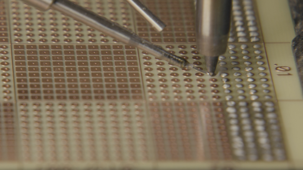
From the view point of the solder paste, the lower the ramp rate the better, usually 1-2°C/s. This is to drive off volatiles and help minimize solder defects such as solder balling, solder beading, and tombstoning. This rate becomes even more important as the solder paste deposit continually decreases in size, as we move to 0201’s and smaller discrete components and from 0.5mm pitch area array packages to 0.4mm and smaller. Due to this miniaturization, the observance of graping and head-in-pillow have become more common. The reflow process window is becoming very narrow and this attribute (ramp rate) has become as important as time above liquidus and peak temperature.
I’d love to discuss this with you, if this topic is affecting your SMT process. If you’d like, feel free to contact me.